FMU Container Builder — GUI
The FMU Container Builder provides a visual, node-graph interface to assemble multiple FMUs into a single FMU Container — without writing JSON or CSV files manually.
Launching the Interface
Or from the FMU Toolbox Launcher, click FMU Container Build.
Interface Overview
The interface is split into three main areas:
| Area | Description |
|---|---|
| Node Graph (left) | Visual canvas where FMU nodes and wires are displayed |
| Tree View (top-right) | Hierarchical structure of containers and FMUs |
| Detail Panel (bottom-right) | Properties of the selected node, wire, or container |
| Button Bar (bottom) | Configuration, load/save, and export actions |
Node Graph
The node graph is the central workspace where you visually compose your FMU container.
Adding FMU Nodes
There are three ways to add FMUs to the canvas:
- Drag & Drop: drag
.fmufiles from your file manager directly onto the canvas. - Right-click → Add FMU…: opens a file dialog to select one or more
.fmufiles. - Tree View → Right-click → Add FMU…: adds FMUs under a specific container in the hierarchy.
Each FMU node displays its filename as a title.
Connecting FMUs with Wires
To create a connection between two FMUs:
- Click and drag from the body of a node (below its title bar)
- Release on another node
- A wire is created between the two nodes
Title bar vs body
- Title bar (top strip with the FMU name): click to select or drag to move the node.
- Body (area below the title bar): drag to create a wire.
The cursor changes on hover to indicate the available action: ✥ for move, ✛ for wire creation.
Wires are directional — arrowheads indicate the data-flow direction:
- Arrow on one end → data flows in that direction (from one FMU to the other)
- Arrows on both ends → bidirectional connection (each FMU feeds the other)
The direction is determined by the port mappings configured in the Wire Details panel.
Reshaping Wires with Waypoints
Wires are drawn as straight-line segments. You can add waypoints to create broken lines and route wires around nodes for better readability.
| Action | How |
|---|---|
| Add a waypoint | Double-click on a wire |
| Move a waypoint | Drag the blue handle (visible when the wire is selected) |
| Remove a waypoint | Double-click on a blue handle |
You can add as many waypoints as needed. The wire becomes a polyline passing through each waypoint in order.
Visibility
Waypoint handles are only visible when the wire is selected. Click on a wire to select it and reveal its handles.
Navigating the Canvas
| Action | How |
|---|---|
| Pan | Middle-click drag, or Alt+Left Button drag |
| Zoom | Mouse wheel |
| Fit all | Right-click → Fit View |
| Select | Left-click on a node or wire |
| Multi-select | Rubber-band selection (left-click drag on empty space) |
| Move node | Left-click drag on a node |
| Delete | Select items, then press Del or Backspace |
Context Menu (Right-click on Canvas)
| Action | Description |
|---|---|
| Add FMU… | Open file dialog to add FMU nodes |
| Delete Selection | Remove selected nodes and wires |
| Info | Show node information and optionally replace the FMU file (single node only) |
| Open in FMU Editor | Open the selected FMU in the Variable Editor (single node only) |
| Open in FMU Tool | Open the selected FMU in FMU Tool (single node only) |
| Fit View | Zoom to fit all nodes in the viewport |
Replacing an FMU
To replace an FMU with a different version or an alternative file:
- Select the node, right-click and choose Info
- The dialog shows the node name and current FMU file path
- Click Browse… to select a new
.fmufile - Click OK to apply the replacement
The replacement is done in place: all wires, start values, and exposed output ports are preserved. If a port name referenced by a start value, a wire mapping, or an exposed output no longer exists in the new FMU, it appears in red in the detail panels — allowing you to review and correct invalid references.
Typical use case
Use this feature when a new version of an FMU is available: replace the file and instantly see which connections or start values need updating.
Tree View
The tree view shows the hierarchical structure of your container assembly.
Root Container
The top-level item represents the output container FMU (default name: container.fmu). All FMU nodes and sub-containers are children of this root.
Sub-Containers
You can create nested containers to organize complex assemblies:
- Right-click → Add Container: creates a new sub-container under the selected item.
- Rename: right-click on a container → Rename.
- Drag & Drop: reorganize nodes and sub-containers by dragging them within the tree.
After renaming a container, the Container Details panel is refreshed immediately to reflect the new name.
Context Menu (Right-click on Tree View)
| Action | Description |
|---|---|
| Add FMU… | Add FMU nodes under the selected container |
| Add Container | Create a new sub-container |
| Rename | Rename a container |
| Delete | Remove a node or container (and all its contents) |
Detail Panel
The detail panel shows the properties of the currently selected element.
Node (FMU) Details
When an FMU node is selected, the detail panel shows:
- FMU name, generator tool, and step size
- Two tabs: Start Values and Output Ports
Start Values tab
Lists all input and parameter ports with their start values.
| Column | Description |
|---|---|
| Input Port | Port name (read-only). Clock and binary ports are excluded. |
| Start Value | User-defined start value (editable). A gray placeholder shows the FMU's default value. |
Start Values
Leave the start value empty to use the FMU's built-in default. Enter a value to override it in the container.
Output Ports tab
Lists all output ports with a checkbox to explicitly expose them at the container level.
| Column | Description |
|---|---|
| Output Port | Port name (read-only) |
| Exposed | Checkbox — when checked, the port is exposed as an output of the container |
When to expose outputs
By default, auto_output automatically exposes unconnected output ports. Use this tab to explicitly select which outputs to expose — useful when auto_output is disabled or when you need fine-grained control.
Port Causality Indicator
Ports are displayed with different text styles to indicate their causality type:
- Parameter ports are shown in italics — these are configuration values or tuning parameters
- Other port types (standard inputs/outputs) appear in regular text
This visual distinction helps you quickly identify parameter ports in the interface.
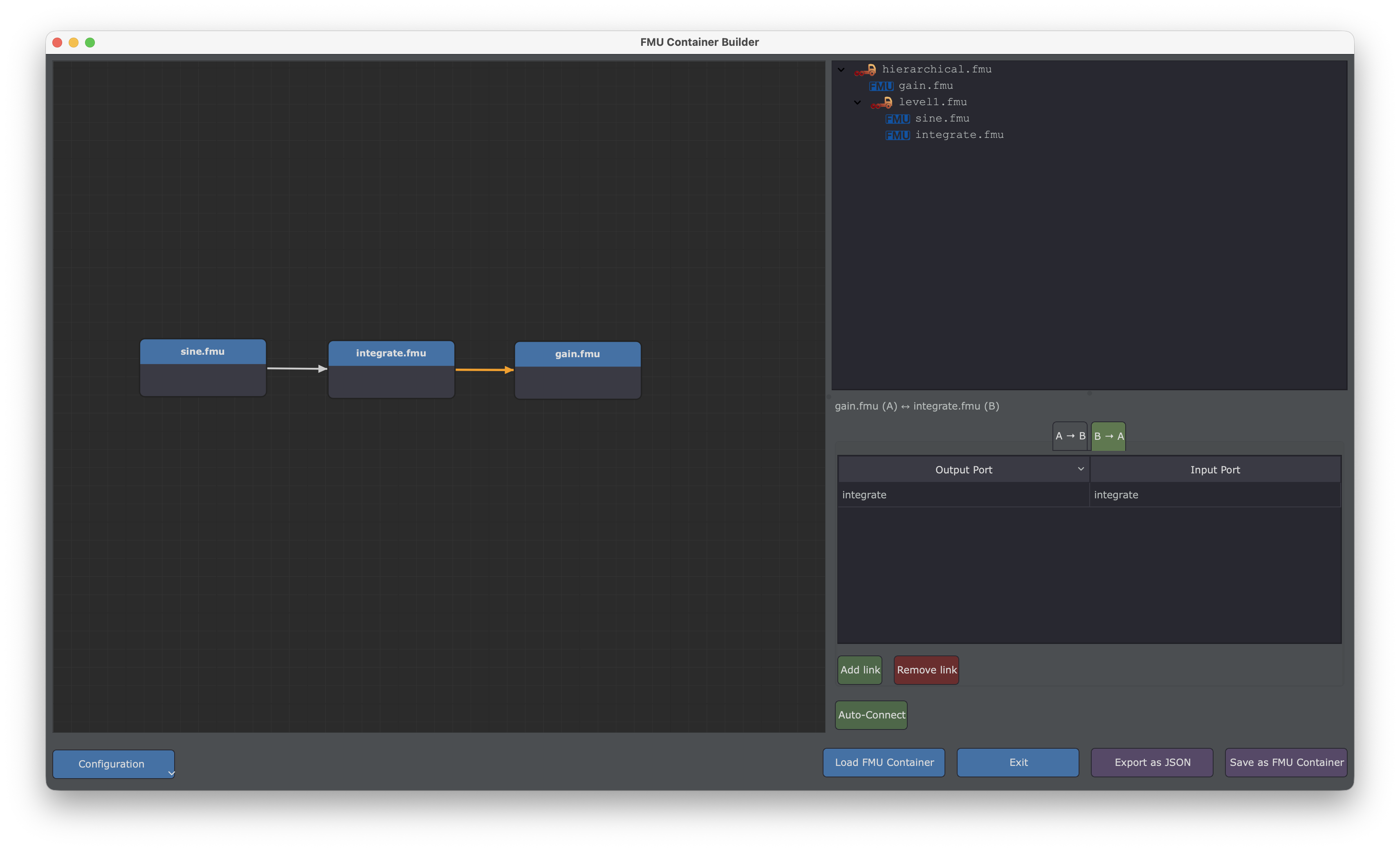
Wire Details
When a wire is selected, the detail panel shows the variable-level mappings between the two connected FMUs.
A header label identifies the two nodes: A = first FMU, B = second FMU.
The mappings are split into three tabs:
| Tab | Description |
|---|---|
| A → B | Output ports of A connected to input ports of B |
| B → A | Output ports of B connected to input ports of A |
| Terminals | Terminal-to-terminal connections (e.g. for LS-BUS enabled FMUs) |
Each tab contains a 2-column table:
| Column | Description |
|---|---|
| Output Port | Output variable of the source FMU (combo-box) |
| Input Port | Input variable of the destination FMU (combo-box) |
Port Causality Indicator
Ports are displayed with different text styles to indicate their causality type:
- Parameter ports are shown in italics — these are typically tuning parameters or configuration values
- Other ports (inputs, outputs) appear in regular text
This visual distinction helps quickly identify parameter ports when configuring mappings.
Each tab has its own Add link / Remove link buttons to manage mappings for that direction.
Terminals tab
The Terminals tab allows connecting FMU terminals (as defined in the FMI LS-BUS standard). Each row maps a terminal from FMU A to a terminal from FMU B:
| Column | Description |
|---|---|
| Terminal A | Terminal name from FMU A (combo-box) |
| Terminal B | Terminal name from FMU B (combo-box) |
This tab is useful when working with LS-BUS enabled FMUs where communication occurs through terminal connections rather than individual variable ports.
The arrowheads on the wire update automatically to reflect the configured directions.
Below the tabs, a global button is available:
| Button | Description |
|---|---|
| Auto-Connect | Automatically map ports that share the same name — in both directions at once |
| Remove All | Remove all link definitions between A and B (both directions) |
| Import | Import link definitions from a CSV file |
| Export | Export link definitions to a CSV file |
Auto-Connect
The Auto-Connect button matches output and input ports by name in both directions — it will create A → B mappings where A has an output matching a B input, and B → A mappings where B has an output matching an A input.
CSV Format for Import/Export
The CSV file uses 4 columns: FMU From, Port From, FMU To, Port To. Each row represents a single port-to-port connection, and both directions (A → B and B → A) are included in the same file. This makes it easy to edit link definitions in a spreadsheet and re-import them.
Container Details
When a container is selected in the tree view, the detail panel shows its configuration parameters:
| Parameter | Type | Description |
|---|---|---|
step_size | text | Fixed time step (in seconds) for the container's internal solver |
mt | checkbox | Enable multi-threading (each FMU runs in its own thread) |
profiling | checkbox | Enable performance profiling of embedded FMUs |
sequential | checkbox | Force sequential execution order |
auto_link | checkbox | Automatically link ports with matching names and types |
auto_input | checkbox | Automatically expose unconnected input ports |
auto_output | checkbox | Automatically expose unconnected output ports |
auto_parameter | checkbox | Automatically expose parameter ports |
auto_local | checkbox | Automatically expose local variables |
ts_multiplier | checkbox | Add a TS_MULTIPLIER input for dynamic step size control |
Button Bar
Configuration
Click Configuration to open a popup menu with:
- Generate FMI-2 / FMI-3: choose the target FMI version for the output container.
- Verbose Mode: enable detailed logging and keep intermediate build artifacts.
- Enable Datalog: include a
datalog.txtconfiguration in the generated FMU (useful for simulation trace export).
Actions
| Button | Description |
|---|---|
| Load FMU Container | Load an existing FMU container (splits it and reconstructs the graph) |
| Import | Import an assembly from a JSON or CSV description file |
| Export as JSON | Export the assembly as a JSON description file |
| Save as FMU Container | Build and save the container as a .fmu file |
| Exit | Close the window (prompts if there are unsaved changes) |
During Load, Import, Export, and Save operations, a progress dialog shows execution logs in real time.
Typical Workflow
Step 1: Add FMUs
Drag and drop your .fmu files onto the canvas, or use the right-click menu.
Step 2: Connect FMUs
Draw wires between output and input ports. Select a wire to configure the port-level mappings in the detail panel. Use Auto-connect to speed up the process.
Step 3: Configure the Container
Select the root container in the tree view to set the time step and other options (multi-threading, profiling, auto-linking, etc.).
Step 4: Organize Hierarchy (Optional)
Create sub-containers and drag FMUs into them to build nested assemblies.
Step 5: Set Start Values and Expose Outputs (Optional)
Select individual FMU nodes and override input port start values as needed. Use the Output Ports tab to explicitly expose specific output ports at the container level.
Step 6: Save
Click Save as FMU Container to build the final .fmu file, or Export as JSON to save the assembly description for later use with the fmucontainer CLI.
Auto-Wiring Workflow
If your FMUs share matching port names (e.g. the outputs of one FMU have the same names as the inputs of another), you can let the container build the connections automatically using the auto_link feature — without manually creating wires.
Step 1: Import your FMUs
Drag and drop your .fmu files onto the canvas, or use the right-click menu to add them. There is no need to draw wires manually between the FMUs.
Step 2: Enable auto_link
Select the container in the tree view (the root item or a sub-container). In the Container Details panel, make sure the auto_link checkbox is checked (it is enabled by default).
This tells the container to automatically connect ports with matching names when the FMU is built.
Step 3: Save the FMU Container
Click Save as FMU Container to build the .fmu file. The auto-linking is performed during the build process: matching output and input ports are connected automatically.
Step 4: Reload to verify
Click Load FMU Container and open the .fmu file you just created. The tool will split the container and reconstruct the graph — this time with all the automatically created wires visible on the canvas. You can select any wire to inspect the port mappings in the detail panel.
Combining manual and automatic wiring
Auto-linking and manual wires can coexist. Any explicit wire you create takes priority. The auto_link option will only fill in the remaining unconnected matching ports.
Loading an Existing Container
Click Load FMU Container to open an existing .fmu container. The tool will:
- Split the container to extract the embedded FMUs and the JSON description
- Reconstruct the node graph with all FMUs, wires, port mappings, and start values
- Restore container parameters (step size, multi-threading, etc.)
You can then modify the assembly and re-save it.
Importing an Assembly File
Click Import to load an assembly from an existing description file. Two formats are supported:
- JSON — full assembly description including container parameters, FMU list, links, start values, and sub-containers.
- CSV — routing table only (FMU list, links, inputs/outputs). Container parameters use defaults.
The tool will:
- Parse the description file using the same engine as the
fmucontainerCLI - Reconstruct the node graph with all FMUs, wires, port mappings, and start values
- Restore container parameters (from JSON) or apply defaults (from CSV)
FMU location
The .fmu files referenced in the description must be located in the same directory as the JSON or CSV file.
Unsaved Changes
If you have unsaved changes when closing the window or loading a new container, you will be prompted to confirm.